Ball bearings are simple, right? Last issue we saw how machines with straight rotating shafts use them to support the shaft while reducing friction so the rotational motion, our useful work, suffers as little as possible from friction. Ball bearings are also used widely and readily because they come as a unit and can be easily added to or removed from a shaft. With lubrication, the friction savings are dramatic and ensuring the alignment of the shaft is correct is easy. However, there aren't many ball bearings inside our favourite machine of all, the internal combustion engine (ICE).

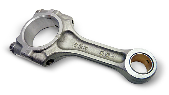
This is because the ICE is complicated and uses lots of parts, almost none of which resemble a straight shaft arrangement. Let us start from the top of the cylinder block. The first place where two parts are moving relative to each other is where the piston meets the connecting rod. The rod transmits the pistons motion to the crank and in the process, the con-rod has to change its orientation to the piston as it rotates the crank. In effect, the reciprocating motion of the piston (a back-forth or up-down repetitive motion) has to be turned into rotating motion at the crankshaft below. The con-rod has to oscillate to do this - swing to and fro. The way we engineer this is by using a gudgeon pin that slides into holes in the piston's skirt through the eye of the (narrow-end of the) con-rod.
The bearings used here look very much unlike ball bearings. They're in fact the pairs of semicircular shells of white metal and circular brass sleeves that are the actual bearings. The gudgeon pin, for example, is usually steel but a brass alloy bush is pressed into the eye of the con-rod, and the friction is mitigated by a combination of the brass ring and forced lubrication. The brass ring is an example of a sleeve bearing.


Connecting rod bearings are semicircular shells of white metal and circular brass sleeves
The other end of the con-rod is called the big-end or the bottom-end. It connects to a crank pin, which is a steel pin that connects two crank webs. Here, the oscillation of the con-rod is changed to rotation. The big-end is formed as two halves that encircle the pin and bolted together. In the middle are semicircular metal alloy shells that are the bearing shells and once again, forced lubrication is applied. The shells are made of alloys of lead, bronze, tin etc. They're a simple design that requires almost no maintenance for most of an engine's life as long as the engine oil and lubrication are correct.
Then comes the crankshaft itself which has to transfer its rotation to the rest of the drivetrain. To ensure that the crankshaft stays aligned and supported as it rotates, it is supported at each shaft (or journal) between two adjacent crank webs. The supporting bearing is called a main bearing. Also called journal bearings, these are also semicircular like the big-end bearings. The crankshaft sits on the lower half of the shells located on the foundation supports just above the sump. The upper shells are placed over it and secured by a bearing cover with bolts. The shells are similar to the con-rod bearings in metallurgy and offer a sliding fit to the crankshaft journal.
This is how the crankshaft is held in position and prevented from direct contact with the block. In operation, the oil forms a thin film between the fine clearances of the shell and the shaft, and friction is reduced drastically. As you can guess by now, the engine's friction management strategy revolves around lubricating the bearings. This is why you want to pay attention to the level and state of your engine oil. Because it has a direct bearing, ahem, on your engine's power and torque.

 Industry News

